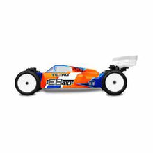
TEKNO EB410 1/10 4WD COMPETITION ELECTRIC BUGGY KIT
Regular price
£285.00
Sale
TEKNO EB410 1/10 4WD COMPETITION ELECTRIC BUGGY KIT.
When designing the EB410, we were entering an even more competitive market. Consequently, our task of creating a new 1/10th 4WD buggy was going to be that much more intense. Our first CAD files for the EB410 date back to August of 2012, before the original EB48 was released. Five years and about two dozen iterations later, we are finally ready to begin talking about specific features of the buggy.
No, the EB410 is not a ‘copy’ of an existing buggy. But we didn’t make it different just for the sake of being ‘different’ either. The decisions made during the design process were carefully considered and thoroughly tested during an extensive prototype phase. Any design aspects that were unsatisfactory during testing were redesigned and retested until we were completely satisfied. The process was quite time-consuming and almost no expense was spared to see our complete vision come to life.
We know this is our most anticipated vehicle to date, which is why we have taken the time to do our homework. We have to release a kit that will truly live up to the Tekno RC reputation for performance, durability, and innovation.
EB410 Key Features:
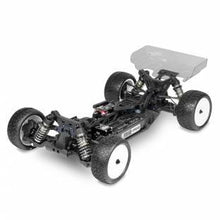
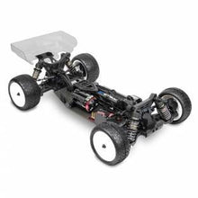
- Three High Volume Fluid Filled Adjustable Differentials
- Ideal Weight Distribution for Modern High Traction Surfaces
- Industry-First 4WD Offroad Reverse Bellcrank Steering System
- 7075 CNC Machined and Lightened Hard Anodized 3mm Chassis
- 7075 CNC Machined Adjustable Hinge Pin Brace System
- 7075 CNC Machined 2-piece Motor Mount System
- 7075 Tapered Lightweight Center Driveshafts
- Heavy Duty 6mm Stub Axles
- Captured CVA Front and Rear Driveshafts
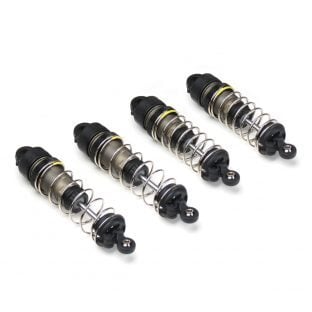
- 13mm Hard Anodized Threaded Shock Bodies
- 3.5mm Shock Shafts with X-Ring Cartridge
- Locking Spring Perch Design
- Downstop Screws for Easy Droop Adjustment
- Quick Access Differentials
- Maintenance Friendly Layout
Shaft-Drive and Differentials:
The first decision to be made was how to get power to the wheels. It was an easy decision for us to choose a shaft-drive system over a belt drive system due to the advantages in durability, efficiency, adjustability, and ease of maintenance. Belts can slip or strip under the load of modern brushless motor systems. The increased friction of belts versus shafts/gears wastes energy, reduces runtime, and hinders top speed. A shaft-drive system easily accommodates a center differential, which is critical for adjusting the front/rear power transfer characteristics. Finally, gaining quick access to all three differentials was one of our goals that could have only been met with a shaft-drive system.
On the topic of differentials, we knew it was going to be important to maximize the internal volume of the diff cases. Increased fluid capacity means the differentials can work more efficiently and consistently. We did not see the point of including a center differential and then basically locking it up with 200K or thicker fluid. With the volume maximized, the resulting tuning window is much larger and can be fine tuned like the differentials used on larger 1/8th scale vehicles.
Driveline:
When it comes to the driveline, achieving maximum efficiency and reducing wear are of utmost importance. Where other buggies may have a twelve degree or higher compound angle driving the front differential, the EB410 has less than one degree. This reduces friction and increases acceleration out of corners.
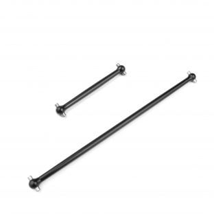
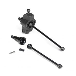
We opted for a bearing-captured CVA drive system to transfer power to the wheels. Aside from ensuring you will not lose a drive pin, it allows for larger inner wheel bearings that increase support and durability of the stub axles. The hefty 6mm diameter hardened steel stub axles are surprisingly lightweight due to extra machining operations. In addition, they make use of our existing hex options for the SCT410.3, allowing for different wheel offsets and track width adjustments. Despite the 6mm axle, we maintain the industry standard M4 wheel nut size ensuring replacement parts are easy to find. Center driveshafts are machined from 7075 aluminum and feature the same tapered design found on the EB48.4 1/8th scale buggy.
Reverse Bellcrank Steering System and Front Bulkhead:
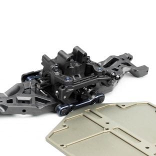
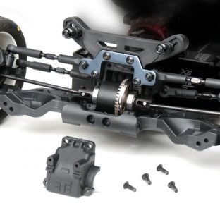
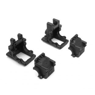
The EB410 incorporates the first reverse bellcrank system available for 4WD off-road 1/10th buggies. It is something 2WD buggies adopted years ago to help smooth out the steering response and improve consistency through the turns. This was no easy feat, but we achieved it by going all out on the front bulkhead design. It is the single most complex part of the EB410, and possibly of our entire history.
We had many goals to meet with the front bulkhead for us to move forward with the rest of the design. Goals such as quick access to the differentials, the ability to completely seal the gearboxes from the elements, a near straight input to reduce center drive angles, durability to survive hard crashes, and finally, a support structure for the entire steering system. The insanely complex mold was manufactured, tested, and fine tuned nearly a dozen times to meet the requirements we set forth. On the track, you will immediately notice how smooth and linear the steering is into and out of corners.
 |
 |
CNC Machined Components:
Anyone familiar with our products knows we put a premium on how the chassis integrates with the rest of the components. We use aircraft-grade 7075 aluminum and high quality hardened steel alloys for all critical parts such as the chassis, hinge pin braces, motor mount, and driveline components.
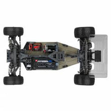
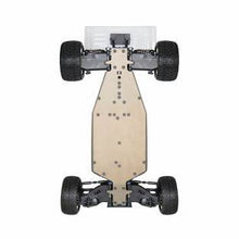
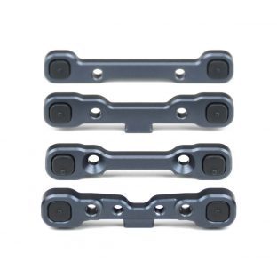
The fully machined chassis has been extensively milled out, not only to reduce weight but also to lower the center of gravity for everything installed in the vehicle. The battery, ESC, and RX all sit 1.5mm below the top surface of the chassis. The adjustable hinge pin brace system is a scaled down version of what you would find in our 1/8th scale line of vehicles. It is easy to adjust and tune, and just as durable as you would expect.
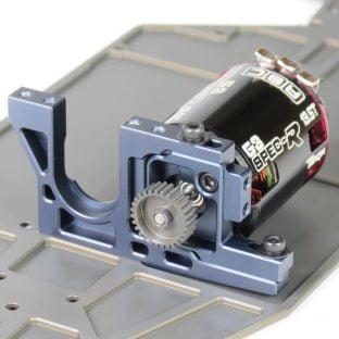
The two piece motor mount system makes gear mesh adjustment and motor removal an easy task. It was designed to produce the lowest center of gravity possible and allows easy access to the center differential without affecting the gear mesh. Lastly, chassis layout places the motor in a location that facilitates the cleanest wiring scheme of any 4WD on the market.
Shocks:
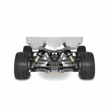
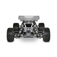
At 13mm, the EB410 shocks are truly big bore. Some might ask, “Why not go with a standard 12mm design?” Our goal was to create an extremely durable and reliable shock system and this meant using 3.5mm shock shafts. But we felt the larger shaft diameter displaced too much oil volume in relation to a 12mm shock body. So in an effort to produce the most consistent shock unit and maintain a high oil capacity, we decided that a 13mm shock body would be best.
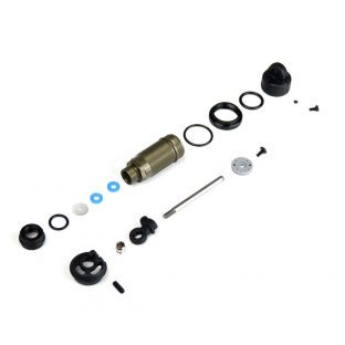
Another 30-year-old throwback that still exists in 1/10th scale offroad is the use of E-Clips to secure shock pistons. Not only is this old technology, it also makes changing pistons and working on shocks an unfriendly affair. We did away with this ancient practice by designing a piston and shaft that tightly integrate together. A custom low profile screw secures the assembly and maximizes stroke length.
A locking spring perch design first seen on our 1/8th scale vehicles makes an appearance on the new buggy. This means your springs will stay firmly seated and in action at all times. An extremely compact shock cartridge combined with low profile shock caps provide class-leading suspension travel while simultaneously making use of shorter shock towers for a lower center of gravity. This enables the EB410 to glide over large bumps and land jumps with complete control.
We felt it necessary to include an easier way to adjust droop on a 1/10th scale vehicle. Droop is an important adjustment that affects how the buggy handles. Until now, you had to either screw or unscrew the shock rod end, or worse, take apart the entire shock to add or remove internal limiters. Racers often look for easier adjustments to make rather than go through this rigamarole, even though adjusting droop may yield the most significant improvements on the track. We accomplished this with the simple addition of droop pads on the chassis and droop screws on the arms.
Chassis and Weight Distribution:
To move the weight forward on a smaller 1/10th scale chassis would require a different approach than 1/8th scale since there is not as much chassis area to work with. Considering the battery would utilize the most space, we first needed to determine what battery types to support. With overwhelming acceptance from customers, manufactures, and the sanctioning bodies, it was a foregone conclusion to settle on a ‘shorty only’ layout for the project. This early decision opened up new possibilities in terms of chassis layout design.
After our team worked through several CAD iterations of the design, we still were not satisfied with where most of the components landed on the chassis. There was more optimization to be made toward the front of the vehicle. We thought if we could just move the bellcranks out of the way, everything could be placed exactly where we wanted. But how?
As noted in part two of our EB410 article series, reverse bellcrank systems have been widely adopted in 2WD vehicles to smooth the steering response and produce a more linear feel. Perhaps it was a natural evolution for 2WD that would never see the light of day in a 4WD shaft driven buggy due to spatial and mechanical limitations.
We kept trying though, eventually figuring out a way to squeeze a reverse bellcrank system into the available space around the front bulkhead and center driveshaft. We thought it was crazy at first and the idea was nearly scrapped, but it was the best solution to meet our design goals. Was it even possible to manufacture? Would it be durable enough? Would it perform on the track? We decided to push the envelope and the respective answers were ‘yes’, ‘yes’, and a lot more ‘yes’.
With the space at the front end of the chassis finally opened up, it was ready to be populated with electronics as evenly and tightly as possible. The steering servo and battery were placed first, dictating where the motor was to be positioned. After a quick check to make sure all of the popular ESC’s and RX’s would fit the remaining space in front of the motor, the basic layout was complete. All of the components closely neighbor one another allowing for the cleanest and most efficient wiring scheme on the market. This also means you will not have the needless weight of power or control wires running across the chassis.
Our design team then focused on making the user experience as friendly as possible. Installing and removing the battery is straightforward with a single thumb screw. The center differential can be removed with only four screws. There is nothing obstructing access to the steering servo, and the front and rear clips can be removed with a minimum amount of screws for easy cleaning. The rear chassis flex is adjustable using two brace options and there are provisions for raising the rear gearbox to suit different track conditions.
Taken as a whole, we have produced a simple, yet beautifully balanced layout optimized for modern track surfaces. We believe it is one of the most advanced 1/10th scale 4WD off-road buggy designs to come along in decades. All this backed by a company committed to vehicle performance, durability, and customer satisfaction.


